
Blog
Object Oriented Analysis and Design (OOAD) Past Paper 2018 – BS 5th Term UOS
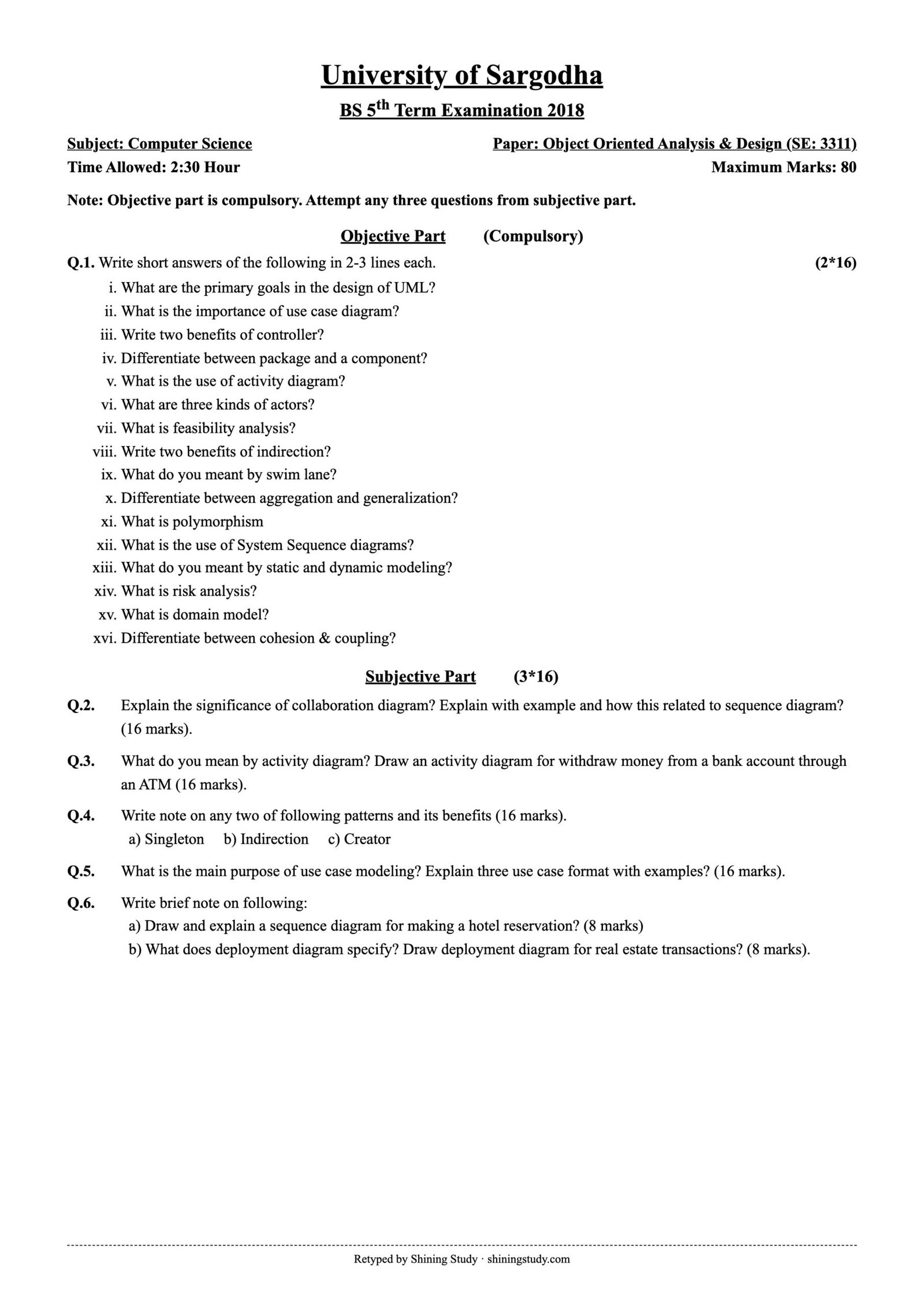
University of Sargodha (UOS) BS 5th term Object Oriented Analysis & Design (SE-3311) past paper 2018, with the full question paper in text form and solved answers, including UML collaboration, activity, sequence and deployment diagrams and GRASP patterns.
Print / download (A4, high quality): Full-size paper
OOAD Past Paper 2018 (text version)
University of Sargodha – BS 5th Term Examination 2018, Subject: Computer Science
Paper: Object Oriented Analysis & Design (SE: 3311) · Time: 2:30 Hour · Maximum marks: 80
Note: Objective part is compulsory. Attempt any three questions from subjective part.
Objective part – Q1: Write short answers of the following in 2-3 lines each. (2*16)
- What are the primary goals in the design of UML?
- What is the importance of use case diagram?
- Write two benefits of controller?
- Differentiate between package and a component?
- What is the use of activity diagram?
- What are three kinds of actors?
- What is feasibility analysis?
- Write two benefits of indirection?
- What do you meant by swim lane?
- Differentiate between aggregation and generalization?
- What is polymorphism
- What is the use of System Sequence diagrams?
- What do you meant by static and dynamic modeling?
- What is risk analysis?
- What is domain model?
- Differentiate between cohesion & coupling?
Subjective part (3*16)
Q2. Explain the significance of collaboration diagram? Explain with example and how this related to sequence diagram? (16 marks).
Q3. What do you mean by activity diagram? Draw an activity diagram for withdraw money from a bank account through an ATM (16 marks).
Q4. Write note on any two of following patterns and its benefits (16 marks).
a) Singleton b) Indirection c) Creator
Q5. What is the main purpose of use case modeling? Explain three use case format with examples? (16 marks).
Q6. Write brief note on following:
a) Draw and explain a sequence diagram for making a hotel reservation? (8 marks)
b) What does deployment diagram specify? Draw deployment diagram for real estate transactions? (8 marks).
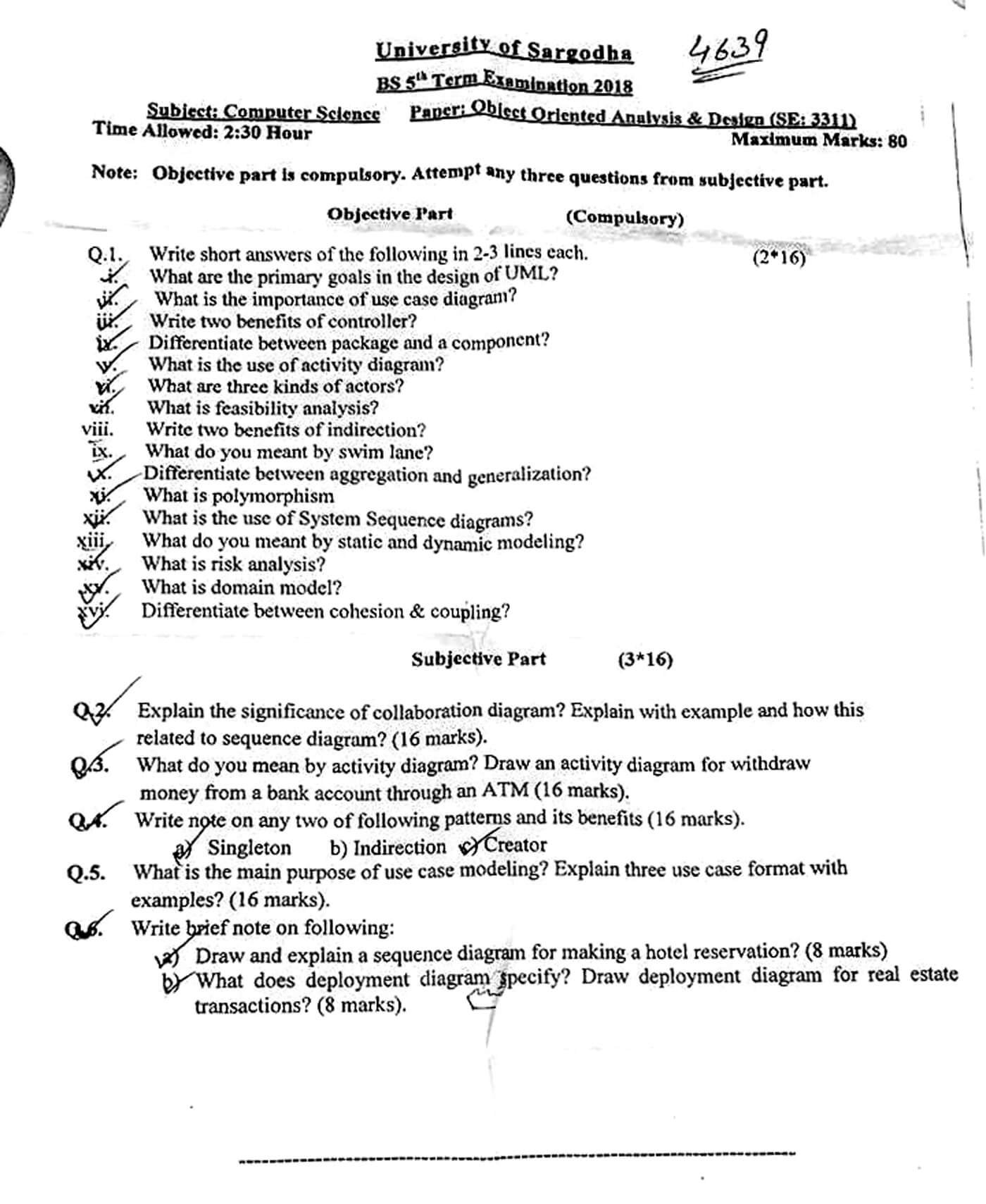
Original paper (scanned copy)
The clean paper above is retyped by Shining Study from this original University of Sargodha question paper. Click the scan to view it full size.
Solved answers
Q1 – Short questions
(i) Goals of UML design: give users a ready, expressive visual modeling language; be independent of programming languages and development processes; provide extensibility (stereotypes, tagged values) and specialization; give a formal basis for understanding the language; encourage the growth of OO tools; and support higher-level concepts such as components, collaborations, frameworks and patterns.
(ii) Importance of use case diagram: shows the system’s functional requirements from the user’s point of view – actors, use cases and their relationships – defines the system boundary, helps communication with clients, and drives design, testing and planning.
(iii) Benefits of the Controller (GRASP): separates the UI from domain logic so the same logic can be reused by different interfaces; gives a single place to control the sequence of system operations and keep state of a use case; increases reuse and pluggable interfaces.
(iv) Package vs component: a package is a logical grouping of model elements (classes, use cases, other packages) used to organize the model and namespaces; it exists only at design time. A component is a modular, replaceable physical/deployable part of the system (e.g. DLL, JAR, service) that realizes interfaces.
(v) Activity diagram use: models the flow of activities in a business process, use case or operation – sequential and parallel actions, decisions, forks/joins and responsibilities (swimlanes).
(vi) Kinds of actors (Larman): primary actor – uses the system to fulfil its goals (Cashier); supporting actor – provides a service to the system (payment authorization service); offstage actor – has an interest in the behaviour but does not interact directly (tax agency).
(vii) Feasibility analysis: studying whether a proposed system is worth building – technical feasibility (can it be built), economic feasibility (costs vs benefits), operational feasibility (will users accept it), and schedule/legal feasibility.
(viii) Benefits of Indirection: reduces coupling between components by adding an intermediate object; components can change or be replaced independently, improving reuse and protecting against variations (e.g. adapters to external services).
(ix) Swimlane: a vertical or horizontal partition in an activity diagram that groups activities by the actor, department or object responsible for them.
(x) Aggregation vs generalization: aggregation is a “whole–part” (has-a) relationship, e.g. a Team has Players (hollow diamond). Generalization is an “is-a” inheritance relationship between a general class and specialized classes, e.g. SavingsAccount is an Account (hollow triangle).
(xi) Polymorphism: the ability of different classes to respond to the same message/operation in their own way; e.g. a draw() call works on Circle and Square objects through a Shape reference, chosen at run time.
(xii) System sequence diagram: shows, for one scenario of a use case, the events that external actors send to the system (treated as a black box) and their order. It identifies the system operations that must be designed.
(xiii) Static vs dynamic modeling: static models show the structure of the system that does not change with time – classes, attributes, relationships, packages (class and object diagrams). Dynamic models show behaviour over time – interactions, states and activities (sequence, communication, state machine, activity diagrams).
(xiv) Risk analysis: identifying possible risks to a project (technical, schedule, cost, requirements, people), estimating their probability and impact, and planning how to avoid, reduce or handle them; iterative processes tackle high-risk items early.
(xv) Domain model: a visual representation of the important conceptual classes (real-world objects) in the problem domain, with their attributes and associations, without software operations – e.g. Sale, Item, Payment in a POS system.
(xvi) Cohesion vs coupling: cohesion measures how closely the responsibilities inside one class/module are related (we want high cohesion). Coupling measures how strongly one class depends on others (we want low coupling). High cohesion and low coupling make software easier to understand, change and reuse.
Q2 – Collaboration (communication) diagram
A collaboration diagram (UML 2: communication diagram) is an interaction diagram that shows objects, the links between them and the numbered messages they exchange to carry out a scenario. It emphasises the structural organization of the objects that collaborate.
Significance: shows which objects work together and how they are connected; helps assign responsibilities and check that a link exists for every message (useful with GRASP patterns); flexible layout – good for showing many objects; message numbering (1, 1.1, 1.2) shows nesting and order; helps find class associations and design the class diagram.
Example – making a payment in a POS system:
1: makePayment(cashTendered)
  :Register --------------------------------> :Sale
                                                |
                                                | 1.1: create(cashTendered)
                                                v
                                             :Payment

  :Register -- 2: getTotal() --> :Sale -- 2.1*: getSubtotal() --> :SalesLineItem
Relation to sequence diagram: both are interaction diagrams that model the same information – objects and the messages between them – and are semantically equivalent; tools can convert one into the other. The sequence diagram emphasises the time order of messages (vertical lifelines and activation bars, easy to read the order, shows creation/destruction clearly), while the collaboration diagram emphasises the relationships/links between objects and uses sequence numbers to show order (space-efficient, flexible but harder to follow for long scenarios).
Q3 – Activity diagram: withdraw money from an ATM
An activity diagram models a workflow as actions connected by control flows, with an initial node (●), final node (◉), decision/merge (◇), fork/join bars for parallel actions and swimlanes for responsibility.
Customer              |        ATM                    |        Bank
-------------------------+-------------------------------+---------------------
 ● Start                 |                               |
 Insert card ----------->| Read card                     |
                         | Ask for PIN                   |
 Enter PIN ------------->| Send PIN for verification --->| Verify PIN
                         |                     <---------|
                         |  ◇ PIN valid?                 |
                         |  [no, < 3 tries] -> Ask PIN again
                         |  [no, 3 tries]  -> Retain card -> ◉
                         |  [yes]                        |
 Select "Withdraw" ----->| Show amount options           |
 Enter amount ---------->| Send request --------------->| Check balance
                         |                     <---------|
                         |  ◇ Sufficient balance?        |
                         |  [no] -> Show "Insufficient funds" -> Eject card -> ◉
                         |  [yes]                        | Debit account
                         | ═══ fork ═══                  |
                         | Dispense cash | Print receipt |
                         | ═══ join ═══                  |
 Take cash and card <----| Eject card                    |
 ◉ End                   |                               |
The decision nodes handle wrong PIN and insufficient balance; the fork/join shows dispensing cash and printing the receipt happening in parallel; swimlanes show who does each step.
Q4 – Patterns
(a) Singleton (GoF): ensures a class has only one instance and provides a global point of access to it. The constructor is private and a static method returns the single instance (created lazily).
public class ServicesFactory {
    private static ServicesFactory instance;          // the one instance
    private ServicesFactory() { }                     // no outside "new"
    public static synchronized ServicesFactory getInstance() {
        if (instance == null) instance = new ServicesFactory();
        return instance;
    }
}
Benefits: controlled access to a single shared object (configuration, logger, factory, connection manager); saves memory; lazy initialization; avoids global variables; can be extended to a fixed number of instances.
(b) Indirection (GRASP): Problem: how to avoid direct coupling between two or more things so that they can change independently? Solution: assign the responsibility to an intermediate object that mediates between them. Examples: an Adapter between the POS system and different tax calculators; a Controller between UI and domain; the Observer pattern; a database mapper between objects and tables.
Benefits: lower coupling, so components can be changed or replaced without affecting others; supports Protected Variations; increases reuse; isolates external systems.
(c) Creator (GRASP): Problem: who should be responsible for creating a new instance of a class? Solution: assign class B the responsibility to create instances of A if B contains or aggregates A, records A, closely uses A, or has the initializing data for A. Example: Sale creates SalesLineItem objects because a Sale contains its line items.
Benefits: supports low coupling (the creator is already connected to the created object), makes the design clearer and reduces dependencies.
Q5 – Use case modeling and use case formats
Purpose: to capture and describe the functional requirements of a system as stories of actors using the system to achieve goals; to define the system scope and boundary; to provide a common language between users and developers; and to drive analysis, design, testing, documentation and iteration planning.
Three formats (Larman):
- Brief: a short one-paragraph summary, usually of the main success scenario. Used early in requirements analysis.
Example – Process Sale: A customer arrives at a checkout with items to purchase. The cashier uses the POS system to record each item. The system presents a running total and line-item details. The customer pays and the system updates inventory. The customer receives a receipt and leaves with the items. - Casual: informal paragraphs covering the main scenario and several alternate scenarios.
Example – Handle Returns: Main scenario: a customer arrives with items to return; the cashier records each item… Alternate scenarios: if the customer paid by credit, the refund goes to the credit account; if the item identifier is not found, the cashier enters it manually… - Fully dressed: a detailed, structured template with all steps and variations. Sections: use case name, scope, level, primary actor, stakeholders and interests, preconditions, success guarantee (postconditions), main success scenario (numbered steps), extensions (alternate flows), special requirements, technology and data variations, frequency of occurrence, open issues.
Example – Process Sale: Primary actor: Cashier. Preconditions: cashier is identified. Main scenario: 1. Customer arrives with goods. 2. Cashier starts a new sale. 3. Cashier enters item ID. 4. System records the line item and shows description, price and running total (repeat 3–4). 5. System presents total with taxes. 6. Cashier asks for payment. 7. Customer pays; system handles payment. 8. System logs the sale and updates inventory. 9. System prints the receipt. Extensions: 3a. Invalid ID – system signals error and rejects entry; 7a. Paying by credit – system authorizes payment…
Q6(a) – Sequence diagram: hotel reservation
Guest          :ReservationUI     :ReservationController    :Hotel        :Room       :Reservation
  |                  |                     |                  |              |              |
  |--searchRooms(dates, type)-->|          |                  |              |              |
  |                  |--findAvailable(dates, type)----------->|              |              |
  |                  |                     |--checkAvailability(dates)----->|              |
  |                  |                     |<----available rooms list------|              |
  |<--show available rooms--|              |                  |              |              |
  |--selectRoom(roomNo)---->|              |                  |              |              |
  |--enterDetails(name, card)->|           |                  |              |              |
  |                  |--makeReservation(guest, room, dates)-->|              |              |
  |                  |                     |--create(guest, room, dates)----------------->|
  |                  |                     |--markBooked(dates)----------->|              |
  |                  |                     |--confirm()------------------------------------>|
  |                  |<--confirmation no.--|                  |              |              |
  |<--display confirmation--|              |                  |              |              |
Explanation: the Guest searches for rooms; the UI passes the request to the controller, which asks the Hotel/Room objects for availability for those dates. The guest selects a room and enters details; the controller creates a Reservation object, marks the room as booked, and returns a confirmation number which is shown to the guest. An alt fragment can show the case “no rooms available” and a payment service lifeline can be added for card authorization.
Q6(b) – Deployment diagram for real-estate transactions
A deployment diagram specifies the physical architecture of a system: the hardware nodes (devices and execution environments), the software artifacts/components deployed on each node, and the communication paths (protocols) between nodes. It is used for planning installation, performance, distribution and security.
<<device>> Client PC / Mobile                 <<device>> Agent Workstation
  [ Web Browser / Mobile App ]                  [ Agent Desktop App ]
              \                                        /
           HTTPS                                     HTTPS
                \                                    /
            <<device>> Web Server (Apache/Nginx)
            [ Property Listing UI, Search ]
                          |
                       HTTP/REST
                          |
            <<device>> Application Server
            [ Listing Service | Offer & Contract Service | Payment Component ]
                 |                                   |
            JDBC/TCP                            HTTPS (API)
                 |                                   |
  <<device>> Database Server                <<external>> Bank / Payment Gateway
  [ Real Estate DB: properties,             [ Payment Processing ]
    clients, agents, transactions ]              |
                                              <<external>> Land Records / Registry Office
Nodes are drawn as 3-D boxes; artifacts inside them; lines show communication paths labelled with protocols. The diagram shows that buyers and agents use browsers/apps, the web and application servers handle listings, offers and contracts, the database stores transaction records, and external systems handle payments and property registration.
Answers prepared by Shining Study for revision. Check them against your class notes and teacher’s guidance.