
Blog
Routing & Switching Past Paper 2017 – MSc IT 4th Term UOS
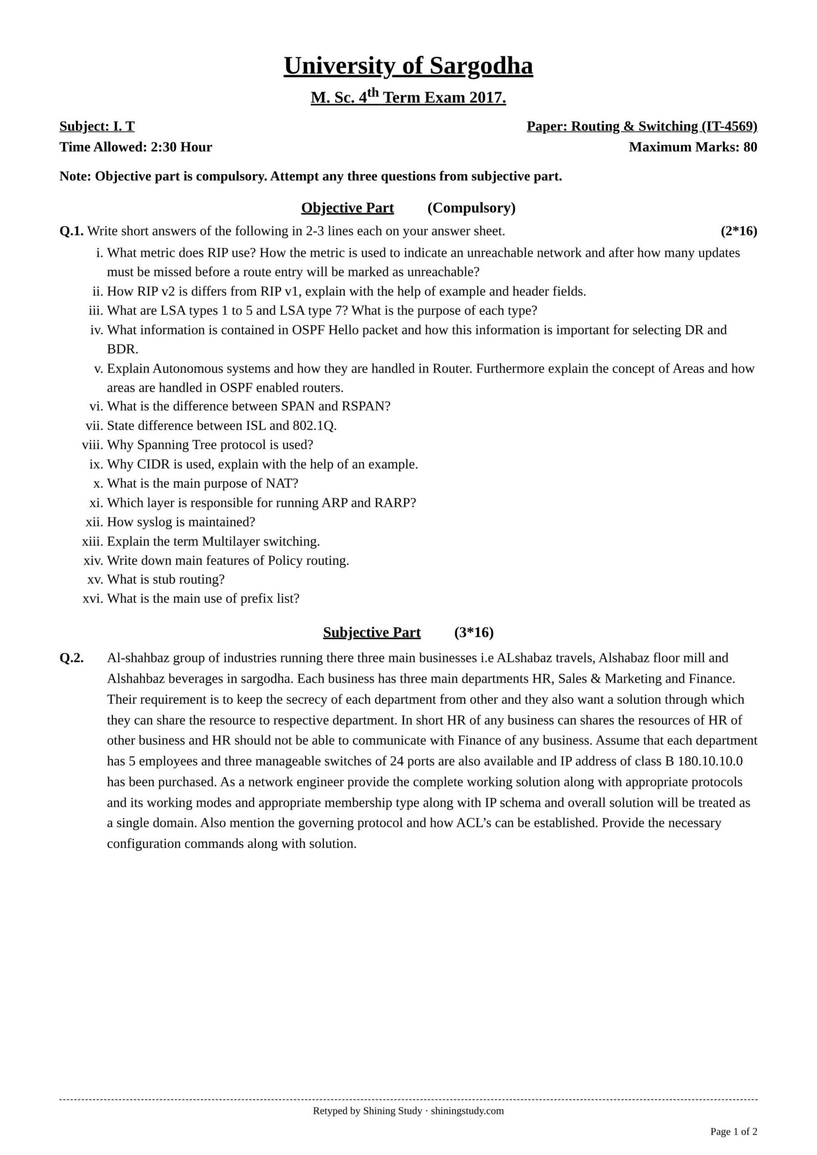
University of Sargodha (UOS) M.Sc. IT 4th term Routing & Switching (IT-4569) past paper 2017, with the full question paper in text form and solved answers, including the VLAN/VTP network design, OSPF shortest path tree and Cisco configuration commands.
Routing & Switching Past Paper 2017 MSc IT (text version)
University of Sargodha – M.Sc. 4th Term Exam 2017, Subject: I.T
Paper: Routing & Switching (IT-4569) · Time: 2:30 hours · Maximum marks: 80
Note: Objective part is compulsory. Attempt any three questions from the subjective part.
Objective part (compulsory) – Q1: Write short answers in 2–3 lines each (2 × 16)
- What metric does RIP use? How is the metric used to indicate an unreachable network, and after how many updates must be missed before a route entry will be marked as unreachable?
- How does RIP v2 differ from RIP v1? Explain with the help of an example and header fields.
- What are LSA types 1 to 5 and LSA type 7? What is the purpose of each type?
- What information is contained in an OSPF Hello packet, and how is this information important for selecting the DR and BDR?
- Explain autonomous systems and how they are handled in a router. Furthermore, explain the concept of areas and how areas are handled in OSPF-enabled routers.
- What is the difference between SPAN and RSPAN?
- State the difference between ISL and 802.1Q.
- Why is the Spanning Tree Protocol used?
- Why is CIDR used? Explain with the help of an example.
- What is the main purpose of NAT?
- Which layer is responsible for running ARP and RARP?
- How is syslog maintained?
- Explain the term multilayer switching.
- Write down the main features of policy routing.
- What is stub routing?
- What is the main use of a prefix list?
Subjective part (3 × 16)
Q2. Al-Shahbaz group of industries runs three main businesses, i.e. Al-Shahbaz Travels, Al-Shahbaz Flour Mill and Al-Shahbaz Beverages, in Sargodha. Each business has three main departments: HR, Sales & Marketing and Finance. Their requirement is to keep the secrecy of each department from the others, and they also want a solution through which they can share resources with the respective department. In short, HR of any business can share the resources of HR of another business, and HR should not be able to communicate with Finance of any business. Assume that each department has 5 employees, three manageable switches of 24 ports are available and the class B IP address 180.10.10.0 has been purchased. As a network engineer, provide the complete working solution along with appropriate protocols and their working modes, appropriate membership type along with the IP schema, and the overall solution will be treated as a single domain. Also mention the governing protocol and how ACLs can be established. Provide the necessary configuration commands along with the solution.
Q3. Provide the topological database, apply the OSPF algorithm on the database and provide the shortest path tree which is derived from that algorithm. Also provide configuration commands for the simplified graph. (Figure: eight routers RA–RH. Links with interface costs at each end: RA–RD 4/4, RD–RG 5/5, RA–RB 2/2, RA–RE 4/6, RD–RE 3/3, RG–RE 1/1, RB–RE 10/2, RE–RH 8/8, RB–RC 1/5, RE–RF 2/2, RC–RF 2/2, RH–RF 6/4.)
Q4. Why is BGP used? Describe the main features and configuration steps of BGP.
Q5. What is the main significance of IP multicast routing? Also mention the configuration steps.
Q6. How is traffic distribution managed with IGMP using multicast IP addresses?
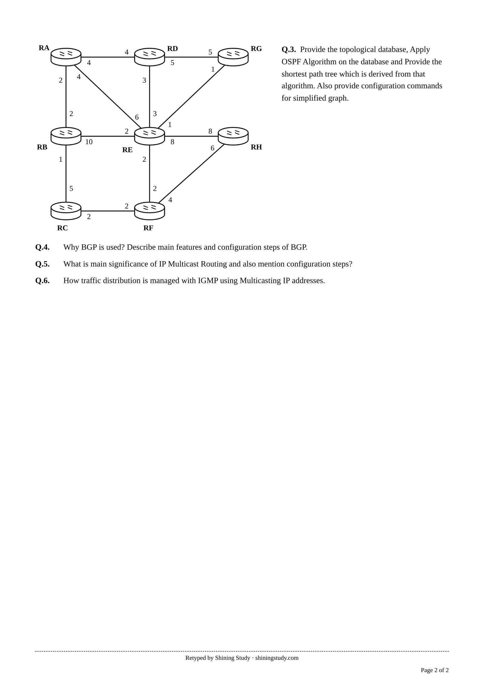
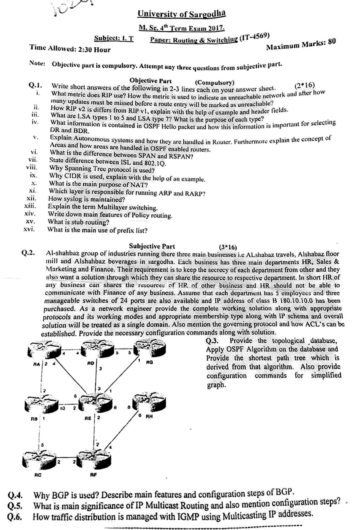
Original paper (scanned copy)
The clean paper above is retyped by Shining Study from this original University of Sargodha question paper. Click a scan to view it full size.
Solved answers
Q1 – Short questions
(i) RIP uses hop count as its metric (maximum 15). A metric of 16 means infinity – the network is unreachable. Updates are sent every 30 s; if no update is heard for 180 s (invalid timer), i.e. 6 missed updates, the route is marked unreachable (metric 16); it is flushed after 240 s.
(ii) RIPv1 is classful: it does not send the subnet mask, broadcasts updates to 255.255.255.255 and has no authentication. RIPv2 is classless: each route entry carries a subnet mask and next-hop field, it supports VLSM/CIDR, uses multicast 224.0.0.9, supports MD5/plain-text authentication and has a route tag field. Example: 10.1.1.0/24 and 10.1.2.0/24 are advertised by v2 with their /24 masks, while v1 would only assume the classful /8. Header: Command, Version (1 or 2), then per route Address Family, Route Tag*, IP Address, Subnet Mask*, Next Hop*, Metric (* = v2 only, unused in v1).
(iii) Type 1 Router LSA – each router describes its links within an area. Type 2 Network LSA – generated by the DR for a multi-access network, lists attached routers. Type 3 Summary LSA – ABR advertises networks from one area into another. Type 4 ASBR Summary LSA – ABR tells other areas how to reach the ASBR. Type 5 AS-External LSA – ASBR advertises external (redistributed) routes to the whole OSPF domain. Type 7 NSSA External LSA – ASBR inside a not-so-stubby area advertises external routes; the ABR converts them to Type 5.
(iv) Hello contains: router ID, area ID, network mask, hello and dead intervals, router priority, DR and BDR addresses, list of neighbours seen, authentication data and stub-area flag. Neighbours must agree on area, mask, timers and stub flag. For election, the router with the highest priority becomes DR (second highest BDR); a tie is broken by the highest router ID; priority 0 means never DR/BDR.
(v) An autonomous system (AS) is a group of networks under one administration and routing policy, identified by an AS number. Inside an AS routers run an IGP (RIP, OSPF, EIGRP); between ASes they use an EGP (BGP), and an ASBR redistributes routes between them. OSPF divides an AS into areas to limit LSA flooding and SPF calculations. Area 0 is the backbone and all areas must connect to it. Internal routers keep the full database of their own area only; an ABR keeps a database per area and summarizes routes (Type 3 LSAs) between them. Configured with network … area n.
(vi) SPAN (port mirroring) copies traffic from source ports/VLANs to a destination port on the same switch for analysis. RSPAN mirrors traffic from source ports on one switch to a destination on a different switch, carrying it across trunks in a dedicated RSPAN VLAN.
(vii) ISL is Cisco-proprietary; it encapsulates the whole frame with a 26-byte header and 4-byte CRC (30 bytes extra) and has no native VLAN. 802.1Q is the IEEE open standard; it inserts a 4-byte tag into the Ethernet frame, supports a native (untagged) VLAN and works between different vendors. ISL is now obsolete.
(viii) STP (802.1D) prevents layer-2 loops in a switched network with redundant links. It elects a root bridge, chooses root and designated ports, and blocks the redundant ports, so broadcast storms, MAC table instability and duplicate frames do not occur; the blocked links become active if a link fails.
(ix) CIDR (classless inter-domain routing) removes class boundaries, so address blocks are allocated by prefix length (saving addresses) and many routes can be summarized into one (smaller routing tables). Example: 192.168.0.0/24 to 192.168.3.0/24 are advertised as one route 192.168.0.0/22; a company needing 500 hosts gets a /23 instead of a whole class B.
(x) NAT translates private (RFC 1918) addresses to public addresses at the border router. Its main purpose is to conserve public IPv4 addresses (many hosts share one address with PAT) and it also hides the internal addressing scheme.
(xi) ARP and RARP map between IP (network layer) and MAC (data-link layer) addresses. They work between layers 2 and 3; in the OSI model they are usually placed at the data-link layer (in TCP/IP they are treated as part of the network/Internet layer).
(xii) Cisco devices send log messages with a severity level 0 (emergencies) to 7 (debugging) to the console, a memory buffer, terminal lines or an external syslog server over UDP 514. Commands: logging host 10.1.1.100, logging trap warnings, logging buffered, service timestamps log datetime; NTP keeps the timestamps accurate.
(xiii) Multilayer switching: a layer-3 switch forwards frames at layer 2 and also routes packets between VLANs at layer 3 (and can use layer-4 information) in hardware (ASICs/CEF) at wire speed. It uses SVIs (interface vlan 10) or routed ports, giving fast inter-VLAN routing without an external router.
(xiv) Policy-based routing (PBR) forwards packets based on administrator-defined policies instead of only the destination address: match on source address, protocol, port, packet size, etc. using route-maps and ACLs; set next hop, interface, IP precedence/QoS; useful for load sharing, separating traffic types and choosing ISPs by source.
(xv) Stub routing: a stub network/router has only one path to the rest of the network, so it uses a default route instead of full routing tables. In EIGRP, eigrp stub makes a spoke router advertise only its connected/summary routes and not be queried, reducing queries and stuck-in-active problems. OSPF stub areas similarly block external LSAs and use a default route.
(xvi) A prefix list filters routes by network prefix and prefix length (ge/le), e.g. in route redistribution, distribute-lists, route-maps and BGP neighbour filtering. It is more efficient and flexible than an ACL for route filtering. Example: ip prefix-list LAN permit 10.0.0.0/8 le 24.
Q2 – Al-Shahbaz network design
Design idea: make one VLAN per department type, spanning all three businesses. All HR staff (15 people) are in VLAN 10, Sales & Marketing in VLAN 20 and Finance in VLAN 30. Users in the same VLAN share resources across businesses, while VLANs are isolated from each other at layer 2. Place one 24-port manageable switch in each business (each has 15 users: 5 HR + 5 Sales + 5 Finance) and connect the switches with trunk links.
- Trunking protocol: IEEE 802.1Q on inter-switch links (mode trunk); access ports in mode access.
- Membership type: static (port-based) VLAN membership – each port is assigned to a department VLAN.
- Governing protocol / single domain: VTP (VLAN Trunking Protocol) with one VTP domain
ALSHAHBAZ. Switch 1 is in server mode (creates VLANs), Switches 2 and 3 are in client mode and learn VLANs automatically. - Loop prevention: STP (Rapid-PVST+) if redundant links are added.
IP schema: each VLAN needs 15 hosts + gateway, so a /27 (30 usable hosts) is enough and leaves room to grow. Subnetting 180.10.10.0:
| VLAN | Department | Network | Usable range | Gateway | Broadcast |
|---|---|---|---|---|---|
| 10 | HR | 180.10.10.0/27 | .1 – .30 | 180.10.10.1 | 180.10.10.31 |
| 20 | Sales & Marketing | 180.10.10.32/27 | .33 – .62 | 180.10.10.33 | 180.10.10.63 |
| 30 | Finance | 180.10.10.64/27 | .65 – .94 | 180.10.10.65 | 180.10.10.95 |
| 99 | Management | 180.10.10.96/27 | .97 – .126 | 180.10.10.97 | 180.10.10.127 |
Switch ports per business: Fa0/1–5 → VLAN 10, Fa0/6–10 → VLAN 20, Fa0/11–15 → VLAN 30, Gi0/1–2 trunks.
! ===== Switch1 (VTP server) =====
hostname SW1
vtp domain ALSHAHBAZ
vtp mode server
vtp password Shahbaz@123
vlan 10
 name HR
vlan 20
 name SALES
vlan 30
 name FINANCE
vlan 99
 name MGMT
interface range fa0/1 - 5
 switchport mode access
 switchport access vlan 10
interface range fa0/6 - 10
 switchport mode access
 switchport access vlan 20
interface range fa0/11 - 15
 switchport mode access
 switchport access vlan 30
interface range gi0/1 - 2
 switchport trunk encapsulation dot1q
 switchport mode trunk
 switchport trunk allowed vlan 10,20,30,99
interface vlan 99
 ip address 180.10.10.98 255.255.255.224

! ===== Switch2 and Switch3 (VTP clients) =====
vtp domain ALSHAHBAZ
vtp mode client
vtp password Shahbaz@123
! same access-port and trunk commands as SW1
! (VLANs are learned from SW1 by VTP)
Inter-VLAN routing and ACLs: if any traffic between departments is needed (e.g. a shared printer or Internet), connect a router to SW1 with router-on-a-stick (or use a layer-3 switch with SVIs). Then apply an extended ACL so HR can never reach Finance:
interface gi0/0.10
 encapsulation dot1Q 10
 ip address 180.10.10.1 255.255.255.224
 ip access-group HR_IN in
interface gi0/0.20
 encapsulation dot1Q 20
 ip address 180.10.10.33 255.255.255.224
interface gi0/0.30
 encapsulation dot1Q 30
 ip address 180.10.10.65 255.255.255.224
 ip access-group FIN_IN in

ip access-list extended HR_IN
 deny ip 180.10.10.0 0.0.0.31 180.10.10.64 0.0.0.31
 permit ip any any
ip access-list extended FIN_IN
 deny ip 180.10.10.64 0.0.0.31 180.10.10.0 0.0.0.31
 permit ip any any
Extended ACLs are placed close to the source (inbound on the sub-interface). If complete secrecy between all departments is required, simply do not route between VLANs, or deny each pair the same way. Port security (switchport port-security maximum 1) can be added on access ports.
Q3 – OSPF topological database and shortest path tree
In OSPF each number beside a router is the cost of that router’s outgoing interface. Every router floods router LSAs, so all routers hold the same link-state (topological) database:
| Router | Neighbours (outgoing cost) |
|---|---|
| RA | RB 2, RD 4, RE 4 |
| RB | RA 2, RC 1, RE 10 |
| RC | RB 5, RF 2 |
| RD | RA 4, RE 3, RG 5 |
| RE | RA 6, RB 2, RD 3, RF 2, RG 1, RH 8 |
| RF | RC 2, RE 2, RH 4 |
| RG | RD 5, RE 1 |
| RH | RE 8, RF 6 |
Dijkstra (SPF) run on RA (the root is not named in the question, so RA is taken as the calculating router). At each step the candidate with the lowest cost is moved to the tree:
| Step | Added to tree | Cost | Via | Candidates updated |
|---|---|---|---|---|
| 1 | RA | 0 | – | RB 2, RD 4, RE 4 |
| 2 | RB | 2 | RA | RC 3 (2+1); RE via RB 12 – worse |
| 3 | RC | 3 | RB | RF 5 (3+2) |
| 4 | RD | 4 | RA | RG 9 (4+5); RE via RD 7 – worse |
| 5 | RE | 4 | RA | RG 5 (4+1) better; RH 12; RF via RE 6 – worse |
| 6 | RF | 5 | RC | RH 9 (5+4) better |
| 7 | RG | 5 | RE | – |
| 8 | RH | 9 | RF | – |
Shortest path tree rooted at RA (total cost in brackets):

RA (0)
 |-- RB (2)
 |    \-- RC (3)
 |          \-- RF (5)
 |                \-- RH (9)
 |-- RD (4)
 \-- RE (4)
      \-- RG (5)
Simplified graph: only links RA–RB, RB–RC, RC–RF, RF–RH, RA–RD, RA–RE and RE–RG are used by RA. Configuration on RA (other routers are configured the same way with their own interfaces and costs, all in area 0):
router ospf 1
 router-id 1.1.1.1
 network 10.0.0.0 0.255.255.255 area 0
!
interface g0/0          ! link to RB
 ip ospf cost 2
interface g0/1          ! link to RD
 ip ospf cost 4
interface g0/2          ! link to RE
 ip ospf cost 4
!
! verify
show ip ospf database
show ip route ospf
show ip ospf neighbor
Q4 – BGP
Why BGP: BGP (Border Gateway Protocol, version 4) is the exterior gateway protocol used to exchange routes between autonomous systems – it is the routing protocol of the Internet. It is used by ISPs and by organizations that connect to more than one ISP (multihoming) and need control over which paths traffic takes.
Main features: path-vector protocol (each route carries the AS_PATH, which prevents loops); runs over TCP port 179 for reliable delivery; sends incremental, triggered updates (no periodic full updates); supports CIDR/route aggregation; policy-based route selection using attributes – weight, local preference, AS_PATH length, origin, MED, next hop; eBGP (between ASes, AD 20) and iBGP (inside an AS, AD 200, needs full mesh or route reflectors); scales to the full Internet table; supports authentication (MD5) and route filtering with prefix lists and route-maps.
Configuration steps: (1) enable BGP with the local AS number; (2) define neighbours and their AS (same AS = iBGP, different = eBGP); (3) advertise networks with the network command (or redistribution); (4) optionally apply policies/filters; (5) verify.
router bgp 65001
 bgp router-id 1.1.1.1
 neighbor 200.1.1.2 remote-as 65002        ! eBGP peer (ISP)
 neighbor 10.1.1.2 remote-as 65001         ! iBGP peer
 neighbor 10.1.1.2 update-source loopback0
 network 180.10.0.0 mask 255.255.0.0
 neighbor 200.1.1.2 prefix-list OUT out
!
show ip bgp summary
show ip bgp
Q5 – IP multicast routing
Significance: multicast sends one stream from a source to a group of interested receivers (class D, 224.0.0.0–239.255.255.255). The sender transmits only one copy and routers replicate packets only where branches split, so it saves bandwidth and server load compared with unicast (one copy per receiver) and avoids flooding everyone as broadcast does. It is used for IPTV, video conferencing, stock tickers, software distribution and routing protocols (OSPF 224.0.0.5/6). Routers build distribution trees (source trees or shared trees rooted at a rendezvous point) using protocols such as PIM (dense mode, sparse mode), and use RPF (reverse path forwarding) checks to avoid loops.
Configuration steps (Cisco, PIM sparse mode):
ip multicast-routing                 ! 1. enable multicast routing globally
!
interface g0/0                        ! 2. enable PIM on every multicast interface
 ip pim sparse-mode
interface g0/1
 ip pim sparse-mode
!
ip pim rp-address 10.0.0.1           ! 3. define the rendezvous point (static, Auto-RP or BSR)
!
interface g0/1                        ! 4. (optional) IGMP version / static join
 ip igmp version 2
!
show ip mroute                        ! 5. verify
show ip pim neighbor
show ip igmp groups
Q6 – Traffic distribution with IGMP and multicast addresses
IGMP (Internet Group Management Protocol) runs between hosts and their local router, so the router knows which multicast groups have members on each LAN segment:
- Joining: a host that wants a stream (e.g. group 239.1.1.1) sends an IGMP Membership Report (join). The router records that group on that interface and, with PIM, joins the distribution tree toward the source/RP.
- Queries: the router (the querier) periodically sends General Queries to 224.0.0.1 (all hosts). One host per group answers with a report; others hearing it suppress their reports, which keeps traffic low.
- Leaving: in IGMPv2 a host sends a Leave Group message to 224.0.0.2; the router sends a group-specific query and, if no one answers, stops forwarding that group onto the segment. IGMPv3 adds source-specific joins (SSM: receive group G only from source S).
- Address mapping: each multicast IP is mapped to a multicast MAC address: 01-00-5E plus the low 23 bits of the IP (e.g. 239.1.1.1 → 01-00-5E-01-01-01). NICs accept only the MACs of groups they joined, so other hosts ignore the traffic.
- Switches: IGMP snooping lets layer-2 switches listen to IGMP messages and forward a group only to ports with members, instead of flooding it to every port in the VLAN.
So traffic is sent only to segments and ports where receivers exist, and it stops as soon as the last receiver leaves.
Answers prepared by Shining Study for revision. Check them against your class notes and teacher’s guidance.